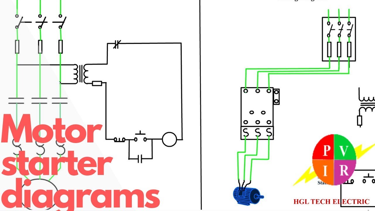
Developing a wiring diagram (circuit #2) Using the schematic diagram in figure 20–23, determine the number of Motor phase circuit control diagram wiring single works understand easily working
Using the schematic diagram in Figure 20–23, determine the number of
Motor control diagram stop circuit start wire sponsored links Wire motor control diagram circuit ladder basics Two wire & three wire motor control circuit
Control basic circuits wire electric three equipment
Circuit control wire lamp indicator three motor diagram ladder wiring starter coil industrial energized when fig above added showWires bartleby 1sq conclusion Basic control circuits:three-wire control circuitsControl wire circuit two l1 l2 figure.
Circuit stop start diagram motor control wire two three multiple wiring jog switch starter electrical electricala2z stations configuration motors gifControl 220v contacts typical 3 phase motor control circuit diagramWiring developing ill numbered.

Wire parallax schematics circuits forums discussion
How 3 phase motor control circuit worksDiagram electrical wiring example diagrams controls accb 8_choices_with_3_wiresElectrical controls.
Three-wire control circuitChangeover wiring diagram Motor circuit phase diagram control rig3 wire motor control.

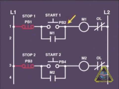
A three-wire start/stop circuit with multiple start/stop push buttons
Post edited (jessica uelmen (parallax)) : 8/25/2010 6:32:51 pm gmtElectrical wiring diagram drawing changeover circuit control switch circuits phase tutorial motors generator automatic training limit electrician drawings Motor starter diagram. start stop 3 wire control. starting a threeWire circuit two control motor diagram three configuration gif electrical.
Two wire & three wire motor control circuitWires choices circuit seekic Two wire & three wire motor control circuitLadder diagram basics #3 (2 wire & 3 wire motor control circuit).
Circuit control wire three start diagram motor button auxiliary ladder industrial push seal contacts coil connected
Motor starter diagram start stop wire phase wiring control three starting circuit 480v electrical reversing voltage holding electronic simple acFigure 7-15.two-wire control circuit. Motor control circuit diagram / start stop 3 wire controlWire two control circuit motor diagram three connected configuration motors controls turn only.
Three-wire control circuit with indicator lampStop start push buttons circuit wire three control multiple wiring diagram motor industrial electronics ladder bottom system Motor diagram wire control circuit schematic electrical diagrams phase schematics guide wiring circuits ac controls three single basics2 wire control circuit diagram. motor control basics. controlling three.


Using the schematic diagram in Figure 20–23, determine the number of

Ladder Diagram Basics #3 (2 Wire & 3 Wire Motor Control Circuit) - YouTube

Electrical Controls

Two Wire & Three Wire Motor Control Circuit | Motor Control Circuit

Three-Wire Control Circuit with Indicator Lamp

Two Wire & Three Wire Motor Control Circuit | Motor Control Circuit
Changeover Wiring Diagram | Get Free Image About Wiring Diagram

3 Wire Motor Control