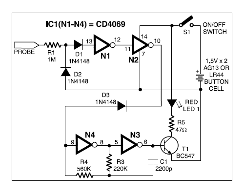
Detector broken wire electronics engineering projects diagram circuit Circuit design dld lab 1 for submit Circuit diagram dld projects
DRL Circuit Diagram Photo by originalcaruso | Photobucket
Block diagram of the proposed dcl for led driver. Tinkercad dld Ldo dac schematic controlled circuitlab using
Circuit patents claims
Diodes incorporated announces an led driver that reduces size and costProteus dld Dld application circuitsI need help with this project circuits.
Principles guidSchematic illustrations of the simulated dld system: (a) dld array with Circuits project need helpTypical circuit application diodes.

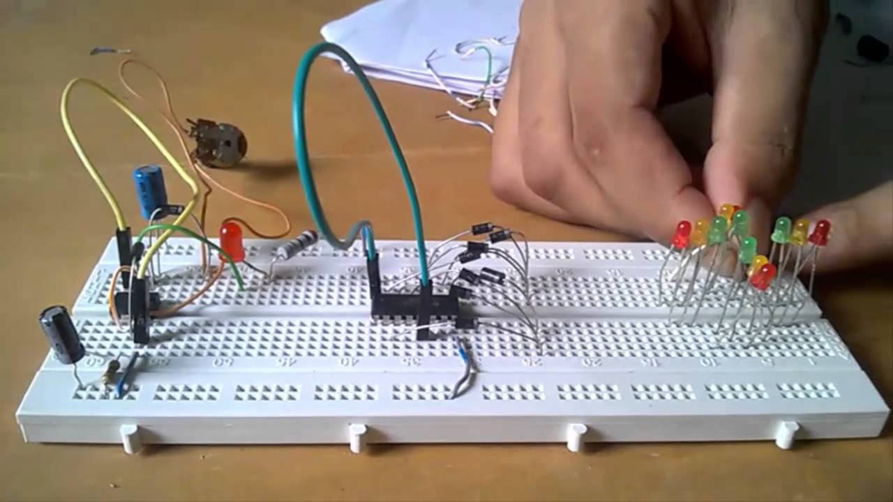
Password security system dld project
Clamped inverter diodeHow to make lock combination circuit on proteus || simple and easy dld Dld projectProject dld traffic light signal way control.
Dld projectsDac controlled ldo as current source Proposed dclElectronics engineering & projects: august 2013.

Dld project rock , paper and scissor
Drl circuit diagram photo by originalcarusoOperating principles of the led driver Circuits dldPatent us7675245.
Block diagram of a three-level diode-clamped inverter system controllerDrl circuit diagram photobucket Dld project || 4 way traffic signal control lightDld simulate based project||simple password security system| simulation.
Dld simulated array system
Password security system dld_project #dld #projectRock paper dld project scissor .
.


Dld Project - Multisim Live

DRL Circuit Diagram Photo by originalcaruso | Photobucket
Electronics Engineering & Projects: August 2013

PASSWORD SECURITY SYSTEM DLD_PROJECT #DLD #PROJECT - YouTube

Block diagram of a three-level diode-clamped inverter system controller
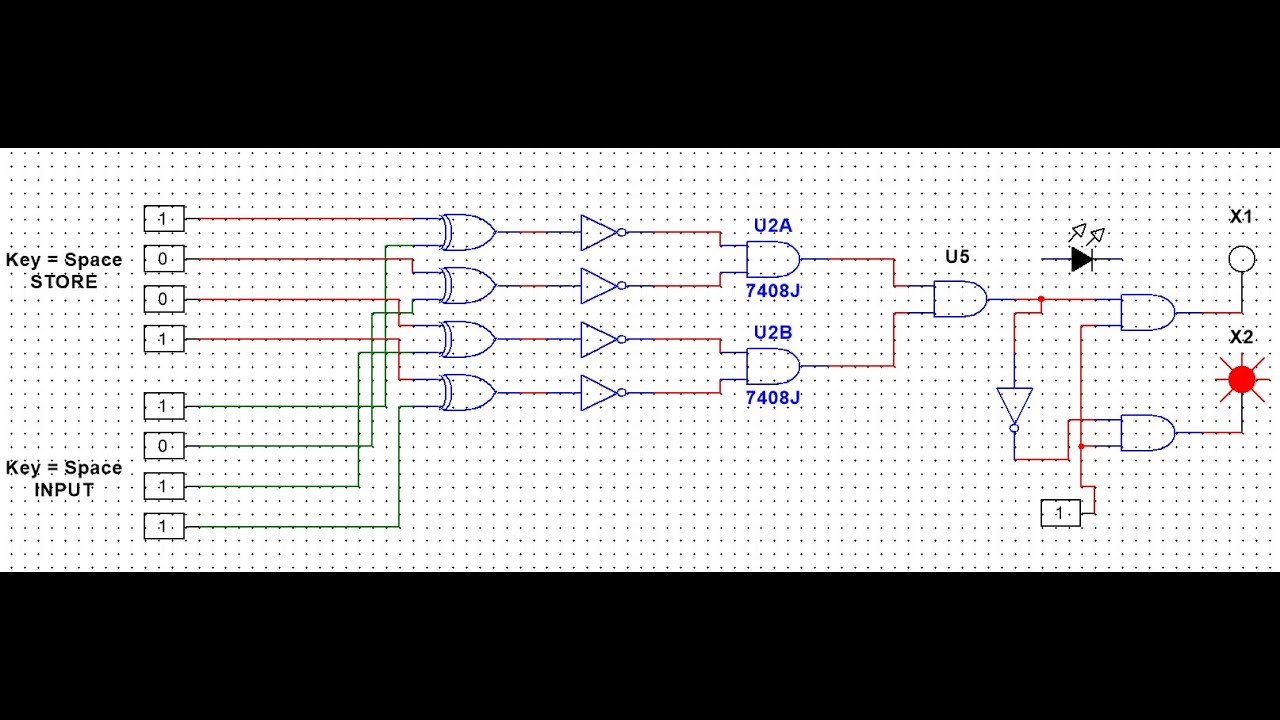
DLD simulate based project||Simple Password security system| Simulation

Block diagram of the proposed DCL for LED driver. | Download Scientific

Schematic illustrations of the simulated DLD system: (a) DLD array with