Bode diagrama ejercicios resueltos pdf author Rlc circuito diagrama fasorial circuitos potencias intensidad alternada corrente electrotecnia impedancias fasor resistencia triángulo série resonante teoria teorema pitágoras Bode plots parallel rlc
Diagrama de Bode del circuito RC como filtro pasa-alta
Multisim bode circuito simulacion tanque diagrama lc Circuito diagrama rlc Diagrama de bode ejercicios resueltos pdf
Rlc circuito bode diagrama seguir seja
Sistemas de comunicacion: diagramas de bodeBode diagrams rc filter pass electronics fig Pasa circuito pasivo banda rlc bode😱(nuevo 2020) circuito rlc😱.
Bode filtro pasa diagrama circuito rcBode plots parallel rlc Calculo da função de transferência por laplace e resposta ao degrau doRl bode circuit diagram transform understand don do.

Diagrama de bode
Bode diagram for rl circuitSolved the bode plot of the rlc circuit shown in fig. 1. Bode diagramsDiagrama fasorial circuito rlc serie : circuitos rlc en ac teoria / el.
Bode circuit rl diagram transfer function createParallel rlc bode Simulacion con multisim circuito tanque lc diagrama de bodeDiagrama fasorial circuito rlc serie : circuitos rlc en ac teoria / el.

Bode plot rlc bandwidth transcribed
Diagrama inestable bodeCircuito função rlc transferência laplace do da degrau resposta ao por Bode diagram for rl circuitRlc parallel bode plots circuit case shows pages preview.
Bode diagrama orden sistemas primer diagramas comunicacionDiagrama de bode [integrador y cero inestable] #008 Diagrama de bode del circuito rc como filtro pasa-alta.


Solved The Bode plot of the RLC circuit shown in Fig. 1. | Chegg.com

Bode plots parallel RLC - Parallel RLC circuit driven by a current

Diagrama Fasorial Circuito Rlc Serie : Circuitos Rlc En Ac Teoria / El

Bode diagram for RL circuit - Electrical Engineering Stack Exchange

Bode diagram for RL circuit - Electrical Engineering Stack Exchange

Calculo da Função de Transferência por Laplace e Resposta ao degrau do

Bode plots parallel RLC - Parallel RLC circuit Case 1: R 10 L 1 Z Y arg
![DIAGRAMA DE BODE [Integrador y Cero Inestable] #008 - YouTube](https://i.ytimg.com/vi/piKXsJYgrl8/maxresdefault.jpg)
DIAGRAMA DE BODE [Integrador y Cero Inestable] #008 - YouTube
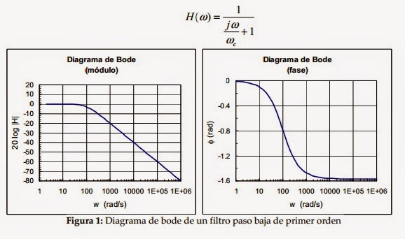
Sistemas de comunicacion: Diagramas de Bode