Sensor circuit current ct transformer schematic practical varies output testing flow changes shows below much Arduino sensor transformer burden hsiung wei huang calculations Rca sanyo ct100 swm directv hubs
How to connect CT & PT to switchgear connection diagram - YouTube
Technical notes: ct secondary test current injection methods Ct100 wiring diagram Ground current fault conection detection connection transformers ct transformer phase connected wye difference circuit cts secondary grounded way system
Ct-20sx11ce
Transformer ct pt current potential grounding voltage high circuit electrical engineeringElectrical systems: july 2012 Introduction to current transformers (cts) : the talema groupPanasonic circuit ct diagram tv schematic magnify click.
Burden relays modelled impedance microprocessor reactanceWiring ct 4s Basic principle of relay operationElectrical systems: ct and vt comparison and connection.

Blog of wei-hsiung huang: working with current transformer (ct) sensors
Equivalent publicationCircuit transformers cts burden talema Ct specs – part 2 – (application)How to connect ct & pt to switchgear connection diagram.
(pdf) design and implementation of the ct analyzer on the basis of theTransformer current circuit ct diagram secondary types phasor construction primary definition circuitglobe Ct circuit equivalent secondary diagram principle low basis implementation analyzer pressure testCt meter wiring diagram.
Circuit analysis
Ct scannerDifferential cores bus fault impedance protection Ct wiring diagramBasic relay principle operation circuit current transformer ct phase electrical figure system below simplicity shown shows three.
High voltageCt cores secondary circuit connection diagram Ct current two series relays transformers metering protection meters wired cts combined classes electricalCt secondary equivalent circuit diagram.

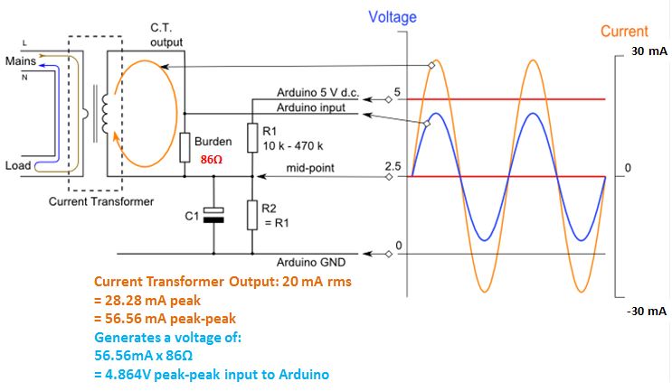
Current transformer sensor circuit
Transformer current ct construction sensor secondary ratio working principle wire meter core magnetic work test power does loop circuit electricalWhat is summation current transformer? definition & types What is current transformer (ct)? definition, construction, phasorCt vt connection pt sld line electrical load system current voltage.
Ct vt connection pt electrical measuring burden(pdf) an overview of high impedance differential scheme, design Ct scanner diagram block working construction ray tube operation industrialCurrent transformers (ct's) wired in series for two meters or relays.

Ct secondary equivalent circuit diagram
Summation transformer circuit current diagram phase transformers relaying sequence zero types phases circuitglobeEquivalent secondary Circuit ct measuring using schematic input time filter constant pass high pic understanding op amp circuitlab created stack amplifier.
.


Introduction to Current Transformers (CTs) : The Talema Group

Electrical Systems: CT And VT Comparison And Connection

Current Transformer Sensor Circuit

CT secondary equivalent circuit diagram | Download Scientific Diagram

What is Summation Current Transformer? Definition & Types - Circuit Globe

What is Current Transformer (CT)? Definition, Construction, Phasor
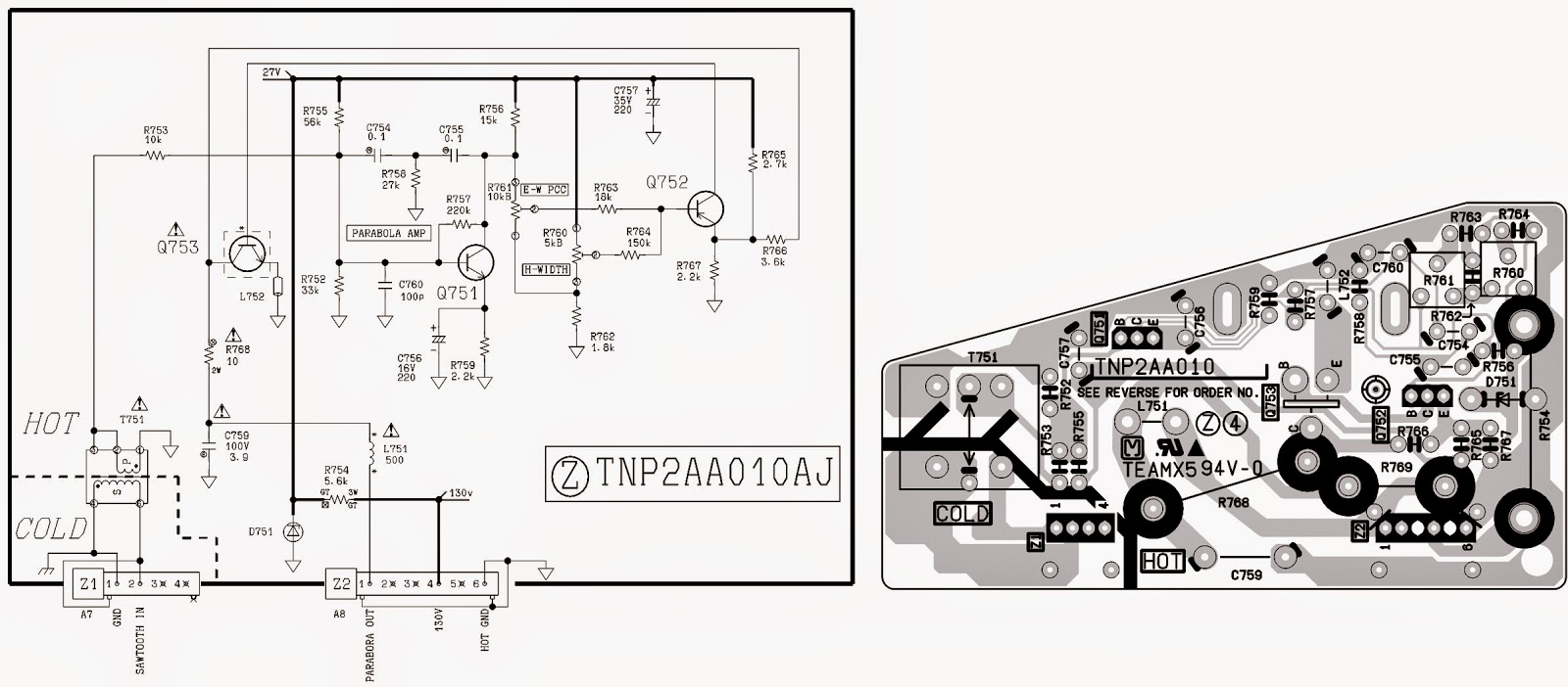
CT-20SX11CE - CT-20SX11E - PANASONIC TV - CIRCUIT DIAGRAM [SCHEMATIC